Build a 5-Axis, Industrial Grade Robotic Arm That Learns (How To)
In this project I will show you how to build a really neat, highly accurate, meter-tall, robotic arm with industrial/memory capabilities that you can make yourself for cheap.
A Quick Preview
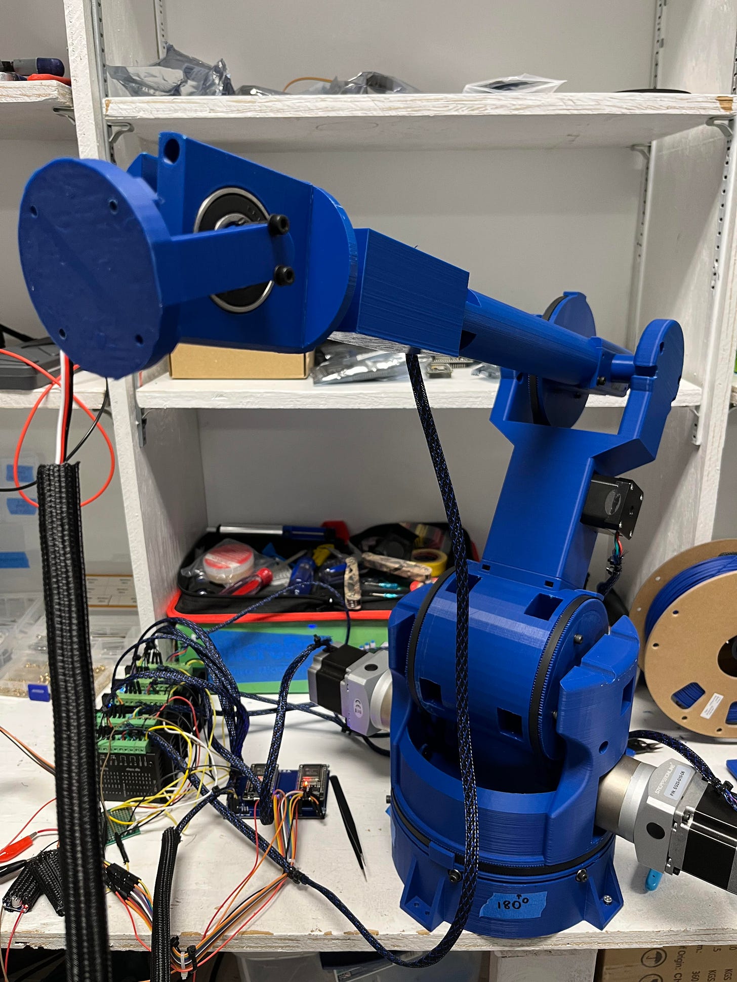
This is E.R.A., the 5-Axis Everything Robotic Arm with built-in position-remembering software and industrial capabilities. It also has an interchangeable end to make it useful for just about any circumstance. I’ve found it to be the perfect assistant in the shop for a variety of uses such as soldering, photography, lighting, and part gripping.
Working Concept
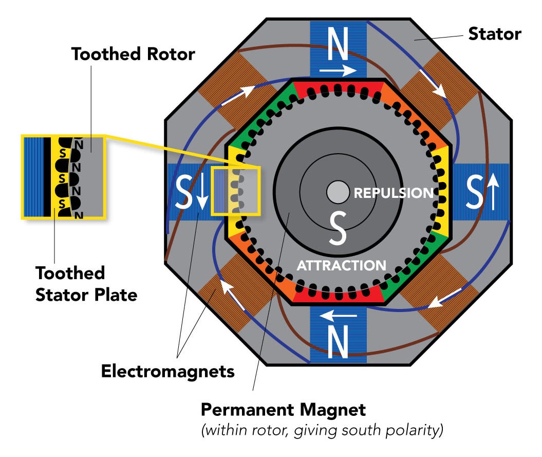
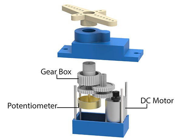
The main concept of how this arm works is that it uses five stepper motors and two servos to move a variety of joints that take advantage of their built in, closed-loop functionalities to remember their position in space and play them back. This can be done due to the unique functionalities shared by stepper and servo motors. This would be their ability to recognize their position in space through potentiometers (servos), and step counting (steppers).
How stepper motors work is the microcontroller (an ESP32 in this case), will send a variety of pulses to a stepper driver which translates those low voltage pulses into high voltage ones which will drive the coils in the stepper motors. In this project we are able to take advantage of that by counting the number of pulses sent to the stepper motor, effectively telling us where the motor is located in the programming.
Servo motors are similar in that they are also able to tell us what their position is, but rather through how far turned their built-in potentiometer is moved. This resistance acts as an encoder and can be communicated to the ESP32. This is also why servo motors are unable to continuously move if you’ve ever wondered. Potentiometers cannot be turned indefinitely!
The Design
When I originally started this design, I wanted it to be different from my last robotic arm in size since the longer it was the higher the value of inertia and inconsistency it had. However, when I first designed it in CAD it was so small and boring… I couldn’t bring myself to follow through with it. Instead, I doubled down and worked twice as hard to make a bigger arm that would still have the accuracy, mobility, and consistency as a smaller/less complex version. I’m glad I did, it’s super awesome now.
I designed ERA based on using GT2 Pulleys to translate the motion from the different motors to the different axes of rotation. I did this since there would be a far smaller dead zone due to the hundreds of teeth on the pulleys, as well as that I knew I would be able to get a good gear ratio from the small pulley wheels on the motors.
Having originally wanted to go for a UR3-ish design, I ended up settling on a 5-axis arm, since I found it insanely easier to manufacture and didn’t want to make it too complex. Now let’s go through the different axes and how they are driven.
The first axis is driven with a NEMA-17 stepper motor with a 15:1 gear ratio using a standard 20-teeth pulley wheel and connecting it around the base.
The second is driven using dual 1.26Nm NEMA-23 stepper motors with a 10:1 planetary gearbox on each one. This is followed by a gear reduction of 3.33:1 through the special 3D-printed pulley wheels I designed for it going up onto the base of the first joint. Just be sure to get the right ones since I’ve found that some manufactures vary in size slightly. I will have the link to the ones I got in the BOM (Bill of Materials) at the bottom.
The third and fourth are quite simple. The third axis, similar to the first, is also driven just through using a NEMA-17 with a 20-teeth pulley wheel going through a slight gear ratio of 9:1 to the base of the second joint.
The fourth is just the wrist axis which requires pretty much zero special attention. It’s just a NEMA-17 with a 27:1 gearbox slapped onto it. However, I’ve honestly found that to be a bit much so feel free reduce it if you’d ever like to use the arm to screw in bolts or anything like that with quicker speed. Just note that a smaller gearbox will yield a smaller torque.
Design Observations and Testing
To test its capabilities, I decided to subject ERA to a variety of strength and accuracy tests.
First, I decided to perform a series of tests to see just how much ERA would be able to lift. When I designed it, I had calculated a 3kg payload given the motor specs. Let’s see how close I got…
It would seem that the belt for the second joint would slip after exceeding a kilogram of stress. However, that doesn’t mean that the actuator would be unable to lift more. You would likely just need to decrease the spacing between the tensors. Since all the other joints worked decently even up until 5lbs, I do believe ERA would be able to lift more if belt slippage was reduced.
UPDATE (04-23-2023 06-16-2023): I have made changes to the CAD files on Thingiverse to fix the slippage issue as well as increase the range of motion for this joint. NEW: I’ve also included a cooling fan for the second joint motor to prevent any plastic deformation due to heat.
As far as accuracy tests went, I decided to iterate through a couple different positions and mark how close they were each time ERA iterated through the motion.
All-in-all, not bad. Especially since I wasn’t very still while holding the camera. In reality, ERA performed better than it seemed in the video. I unfortunately didn’t make a second robotic arm to record my robotic arm, yet…
Overall, I’m satisfied with how all the tests went. Payload can be increased exponentially with a few minor tensor adjustments and accuracy was measured to be within +-2mm over multiple iterations.
The Hardware
The hardware you will need for this project are some TB6600 stepper motor drivers, ESP32 microcontrollers, a 24VDC power supply, some 24-AWG wires for powering the steppers, and some sort of board to distribute the different connections. (All can be found in the BOM.)
Luckily for you, I have already designed a fully functional PCB (Printed Circuit Board) that you can have access to for free to use in your project.
Just as a note: The big green board you see in some of the assembly/testing videos appears different because it is an old design. This one operates much smoother and is plug and play.
UPDATE (05-12-2023 06-16-2023): If you would like to run inverse kinematics and other more advanced software, please create the board detailed in this post, as it would be able to run these more advanced functionalities. If you would only like to use the functions described in this article, however, this board is fine.
PCB Gerber File: Here (Click on download toward the bottom right once on GitHub)
This board will distribute all the different servo motor/DIR and PUL signals from your microcontroller to your stepper motor drivers as well as supply power for the servo and microcontrollers. In addition, the board comes with a handy power indicator LED and 10uF capacitor for each ESP32 to protect them from any voltage irregularities.
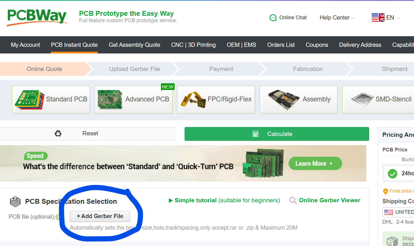
For ordering the board, I decided to go with PCBWay. They have a steal at $5 for 5 boards and I was pretty impressed with how easy the process was. All I had to do was go to PCBWay.com, click on quick-order PCB, and upload the Gerber file. Or alternatively, just go here which I have saved in my favorites bar.
I decided to go with a blue solder mask to match the color of the robotic arm.
The boards arrived just a few short days later and looked fantastic! They had a really nice finish which I loved, the solder mask was beautiful, and they all functioned remarkably without any problems.
Now that I had a quality PCB and didn’t have to worry about any finicky connections anymore, I could continue working on ERA.
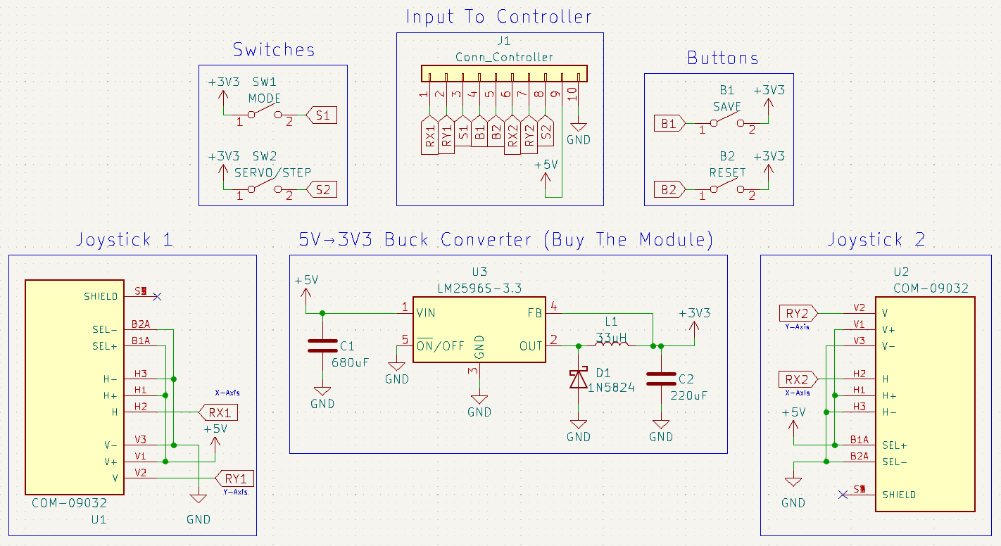
Something important that you need to note is that you will need some sort of controller for controlling the arm's different joints. I made a pretty simple one just from a protoboard at my house, 2 joystick modules, 2 buttons, and 2 switches.
UPDATE: You can 100% use the Universal Controller for this and it’d work fantastically!
Feel free to copy the schematic of mine above or make your own. All you really need are some potentiometers and buttons. There are not really any strict guidelines here. You could even hook up an old Xbox/remote-control car controller if you’d like. Just make sure they have a common ground!
NOTE: The ESP32 is only there in case I ever wanted to make it wireless. It doesn't need to be there. I also added extra buttons/switches, they aren’t necessary for this project.
The two joysticks are for moving around the different joints on the arm (left is the base and first joint, right is second joint and wrist). The first button is for whenever you want to save ERA’s current position, and the second is for when you want to reset all the positions. For the switches, the first is the mode (ON means user control, OFF means playback), and the second is to swap the second joystick’s control to the 5th axis and optional attachment servo.
Demo as shown earlier:
Connecting The Electronics
All the connections for the electronics are pretty simple once you have your PCB and controller made. All you have to do is connect each stepper motor coil to the A+-/B+- on the stepper motor driver, connect the GNDs to ground, and connect each respective DIR and PUL pin to that labeled on the PCB. For the stepper motor coils, it typically goes blue > red > green > black.
To connect the wrist servo motor, just connect the power and GND to that on the PCB under Wrist Servo. You can also connect the optional accessory servo to its place on the PCB if you choose to use it for something.
NOTE: Accessory Servo is an optional servo motor I pre-programmed in for you all in case you ever need a servo to operate a gripper, etc. If you don’t need it, just ignore it. It won’t hurt anything. The wrist servo is the main one that operates that wrist axis.
To connect the controller, each label is assigned as follows:
RX1: X-axis, first joystick (leftmost one).
RY1: Y-axis, first joystick (leftmost one).
RX2: X-axis, second joystick (rightmost one).
RY2: Y-axis, second joystick (rightmost one).
B1 & B2: Button 1 and 2.
S1 & S2: Switch 1 and 2.
Power and GND.
Programming the ESPs
I wrote everything for the robotic arm using Arduino C++. This comes standard in the Arduino IDE.
The code for ESP1 can be found by clicking here.
The code for ESP2 can be found by clicking here.
(You may need to change the mapped values for the servo motors in the ESP2 program depending on the servo motor shaft orientation when being mounted! This also goes for the joystick controls for both programs.)
Feel free to either download the GitHub file linked above or just simply copy and paste the code over into your Arduino IDE.
I’m only going to explain the code for the first one (ESP1) since it’s essentially the exact same program just with different pin assignments and integer names.
Anyway, here’s how the code works.
#include <AccelStepper.h> This imports the AccelStepper library which you will have to download to make this project work. This can be done easily by going to tools > manage libraries > type in AccelStepper > click on install.
Also, make sure you have the proper ESP32 board selected. I’ll direct you to this helpful article on that if you haven’t already set that up.
Next, you declare the different data types.
const int button1Pin = 22;
const int button3Pin = 4;
const int switch1Pin = 33;

const int xAxisPin = 34;
const int yAxisPin = 35;

const int h1atPositionPin = 21;
const int h2atPositionPin = 17;

int baseStepperSpeed;
int j1StepperSpeed;
int maxSpeed = 1000;

int basePositions[10];
int j1Stepper1Positions[10];
int j1Stepper2Positions[10];
int posCount = 0;

int delayPositions[10];
int delayPositionsCount = 0;

unsigned long previousMillis = 0;
int timeDelay = 0;

bool dontLoop = false;
bool saveButtonHit = false;
bool replay = true;
Notice how in I declared the different arrays to hold 10 different integers.
int basePositions[10];
int j1Stepper1Positions[10];
int j1Stepper2Positions[10];
int delayPositions[10];
This dictates how many positions the program will be able to remember. Right now, it’s set to 10. If you’d like for ERA to remember more positions, feel free to increase the number to whatever you desire. Just note that ESP32s don’t have a bunch of memory and it may lead to problems if you set it too high.
Next, you assign values to the different steppers in the AccelStepper class.
AccelStepper baseStepper(1, 13, 12);   // (Type:driver(1 is default driver), STEP, DIR)
AccelStepper j1Stepper1(1, 15, 14);   // (Type:driver(1 is default driver), STEP, DIR)
AccelStepper j1Stepper2(1, 19, 18);   // (Type:driver(1 is default driver), STEP, DIR)
In doing so, you also must set the maximum speed in steps per second.
baseStepper.setMaxSpeed(maxSpeed);  //400 pulse/rev
j1Stepper1.setMaxSpeed(maxSpeed);  //200 pulse/rev
j1Stepper2.setMaxSpeed(maxSpeed);  //200 pulse/rev
Then you declare the different pin modes so the ESP32 knows which signals are going out/in. I set my inputs to an internal pulldown resistor to filter out noise.
pinMode(xAxisPin, INPUT_PULLDOWN);
pinMode(yAxisPin, INPUT_PULLDOWN);
pinMode(h1atPositionPin, OUTPUT);
pinMode(h2atPositionPin, INPUT_PULLDOWN);
pinMode(switch1Pin, INPUT_PULLDOWN);
pinMode(button1Pin, INPUT_PULLDOWN);
pinMode(button3Pin, INPUT_PULLDOWN);
Here, I set the variable currentMillis to the internal milliseconds clock built in to the ESP32. This is important because it allows us to keep time. This will be nice since we may want ERA to remain in specific positions for given amounts of time before moving.
unsigned long currentMillis = millis();Now we write a simple if statement that will call user control functions if switch1 is on. (If switch is HIGH, user control mode.)
if (digitalRead(switch1Pin) == HIGH)
  {
    baseStepperJoystickControl(xAxisPin, baseStepperSpeed);
    j1StepperJoystickControl(yAxisPin, j1StepperSpeed);
If button3 is pressed while in user control mode, reset all the arrays.
if (digitalRead(button3Pin) == HIGH) //Reset
    {
      memset(basePositions, 0, sizeof(basePositions));
      memset(j1Stepper1Positions, 0, sizeof(j1Stepper1Positions));
      memset(j1Stepper2Positions, 0, sizeof(j1Stepper2Positions));
      memset(delayPositions, 0, sizeof(delayPositions));
      stepperCount = 0;
      delayPositionsCount = 0;
      timeDelay = 0;
    }
If button1 is pressed while in user control mode, save the positions to the first available position in each of their arrays.
if (digitalRead(button1Pin) == HIGH && dontLoop == true)
    {
      basePositions[stepperCount] = baseStepper.currentPosition();
      j1Stepper1Positions[stepperCount] = j1Stepper1.currentPosition();
      j1Stepper2Positions[stepperCount] = j1Stepper2.currentPosition();
      stepperCount++;
      delay(100);
      previousMillis = currentMillis; //Start clock
      saveButtonHit = true;
      dontLoop = false; //Local variable to make sure only one position saved
    }
I used the saveButtonHit variable to ensure that the entire next statement would execute regardless of any changes in the button or switch state.
Now, we will start an internal clock and only stop it once the arm starts moving. This part of the code can seem a bit tricky so stick with me.
if (saveButtonHit) //So entire statement will execute
    {
      if (baseStepper.currentPosition() == basePositions[stepperCount-1]) //If still
      {
        timeDelay = currentMillis - previousMillis;
        delayPositions[delayPositionsCount] = timeDelay;
      }
      else
      {
        delayPositionsCount++;
        saveButtonHit = false;
      }
    }
In the code above, we use an if statement to check if the currentPosition is equal to the position it was at when the save button was pressed. If it is, it is essentially at rest, and we start a clock by setting the timeDelay variable to the amount of time that has passed since it arrived at that position. That is then saved to an array corresponding to the position it is at. When the arm moves from that position, it updates the count and exits the statement. Notice how baseStepper is used to dictate if the arm is in motion. On the other ESP32, this would be the wristStepper. This means you need to move these at the same time whenever you want to exit from a position. If they are offset, the motion will be wrong.
Next comes the playback through positions part of the program.
First, we check if switch1 is off.
else
  {
    while (digitalRead(switch1Pin) == LOW)
    {
      for (int i = 0; i <= sizeof(basePositions) / sizeof(basePositions[0]) && digitalRead(switch1Pin) == LOW; i++) //using basePositions as base array
      {
If it is, loop it and iterate through a for loop of all the different saved positions. I decided to use the basePositions array as a reference since they all are the same size.
In the for loop, this code moves each motor to the position it was at when the save button was pressed. I also used an if statement to iterate back from the beginning of the for loop if you reached the end of the array (didn’t use all 10 positions).
if (basePositions[i] == 0) //Back to 0 at end of array
          i = 0;

baseStepper.moveTo(basePositions[i]); //Set target positions
baseStepper.setSpeed(500);
j1Stepper1.moveTo(j1Stepper1Positions[i]);
j1Stepper1.setSpeed(500);
j1Stepper2.moveTo(j1Stepper2Positions[i]);
j1Stepper2.setSpeed(-500);
You can use a while loop to run each stepper to its position at the same time. (While not at position, move to position.) Something else to note is that I wrote a LOW digital signal to h1atPositionPin whenever they were not at their requested position. This is because we have to tell the other ESP32 to wait until they get there. Without this, the movements between the different ESP32s would be offset.
while (j1Stepper1.currentPosition() != j1Stepper1Positions[i] || j1Stepper2.currentPosition() != j1Stepper2Positions[i] || baseStepper.currentPosition() != basePositions[i])
        {
          digitalWrite(h1atPositionPin, LOW);
          baseStepper.runSpeedToPosition();
          j1Stepper1.runSpeedToPosition();
          j1Stepper2.runSpeedToPosition();
        }
digitalWrite(h1atPositionPin, HIGH);
The other ESP32 communicates their positions the same way using their own digital signal across h2atPositionPin. This code segment pretty much just means do nothing until other ESP32 communicates its motors are at their position.
while (digitalRead(h2atPositionPin) != HIGH) //Wait for other steppers
        {
          //Do nothing
        }
When they are, the while loop will exit, and all the motors will wait for however long it was when ERA wasn’t moving during user control. (timeDelay value).
delay(delayPositions[i]);Assembly
Before we get started, please make sure you have all the desired cad files downloaded from the BOM. Something important to note is that I printed all of mine on a 300x300x340mm print bed. If your 3D-printer cannot print that large, feel free to modify the CAD files into smaller segments and add places to attach them together with bolts. There will be a STEP file attached so you all can modify/remix the arm as you wish, I only ask you credit me.
Now, let’s get started.
The first thing we will want to assemble is the base plate of the robotic arm. There is a spot on the print to attach a NEMA-17 stepper motor. After screwing that in, you will want to attach a pulley wheel up toward the top of the motors shaft. We can mount it by just screwing in the M2 bolts that come on it.
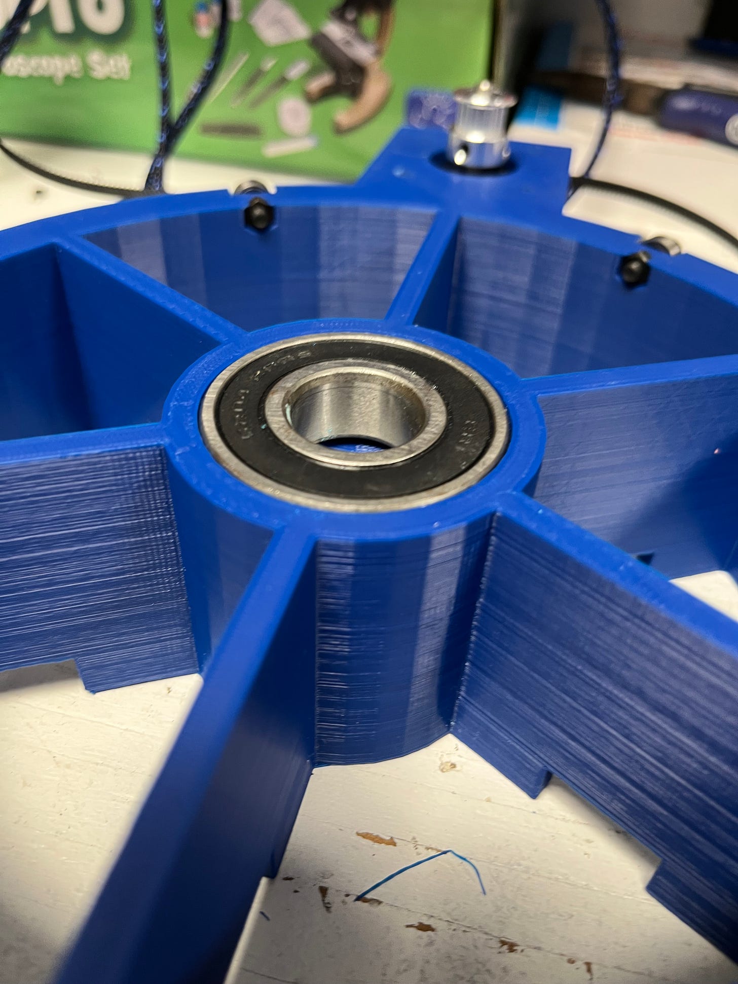
After that, we are going to want to attach all the bearings. We will use one of our larger 20x47x14mm bearings to allow the rest of the robotic arm to rotate about that axis. We can mount it by press fitting it with a clamp or other tool.
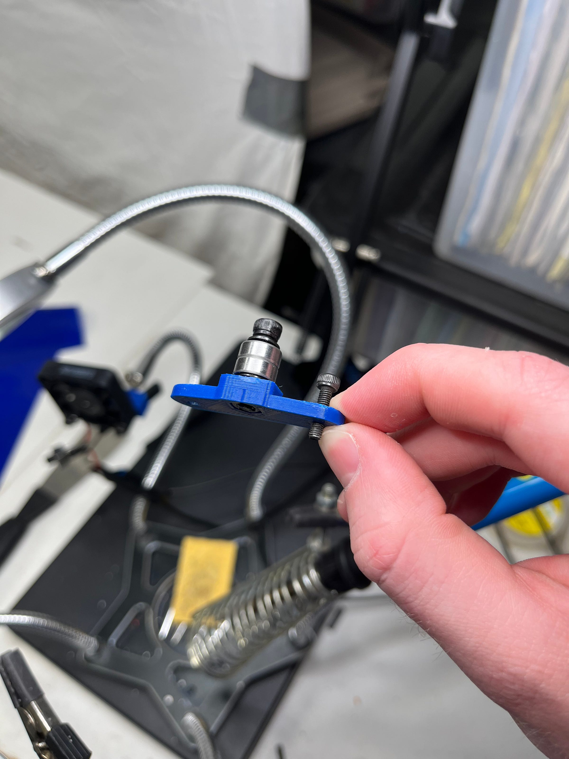
The next bearings we will want to attach are the smaller 4x10x4mm bearings. These will allow the arm to rotate smoothly over the base plate. We can mount these just by placing a M4 nut on the inner ring, then screwing a small M4 bolt through it.
Now, we’ll add the next piece. Go ahead and insert the base component by just smoothly sliding it into the bearing hole we previously mounted with the 20x47x14mm bearing.
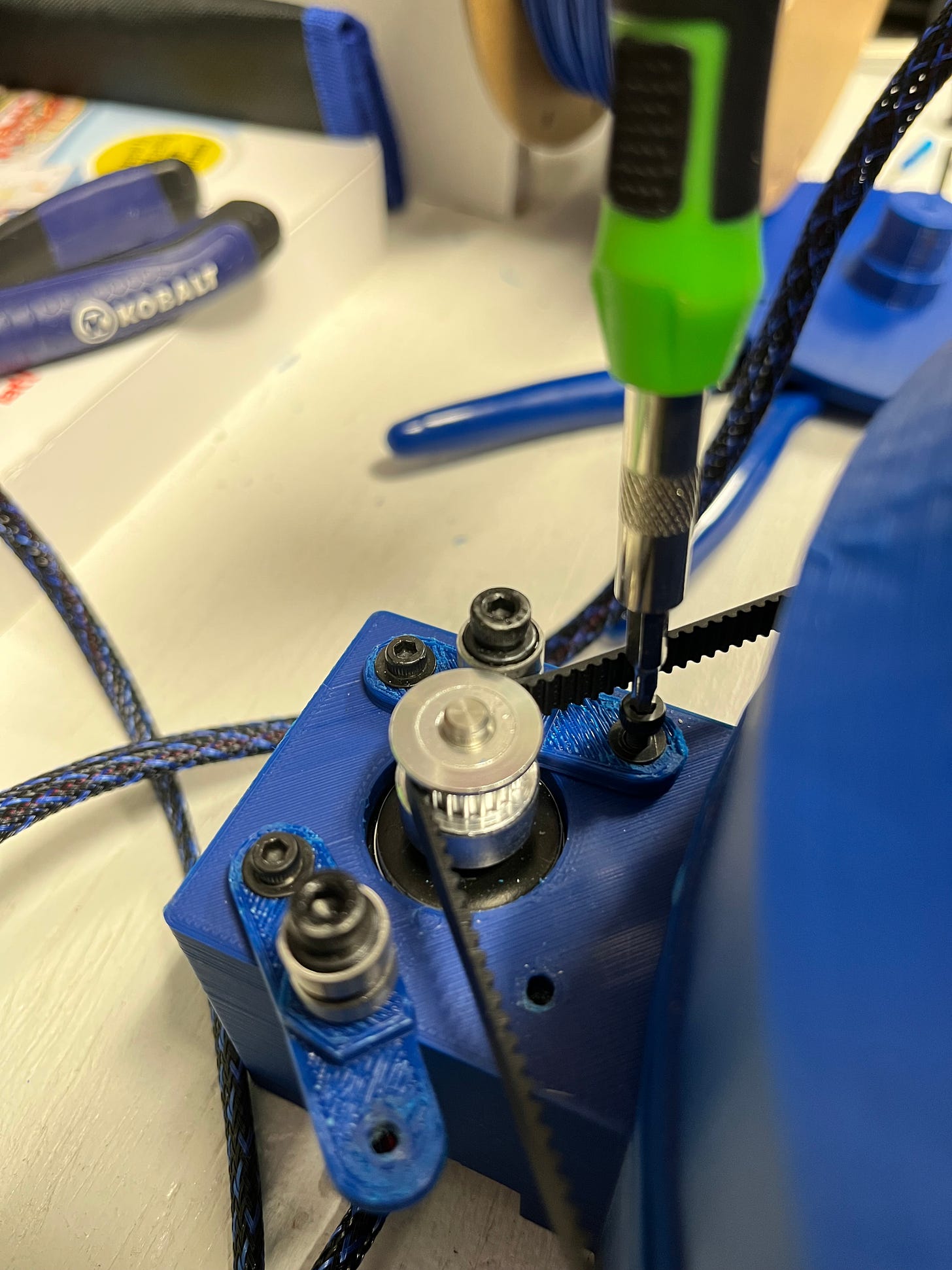
After that is all done, it’s time to attach the timing belt. All we need to do for this is wrap the belt around the axis of the base and the NEMA-17 pulley wheel, then tuck it into the fitted area to secure it in place. Make sure the belt length is as short as possible while still being able to fit it.
After that, screw the bearings on the tensor. Just place the M4 nut on the inside of the tensor, place your bearing, and thread through with a M4 bolt to mount it. After that, screw them into the base plate. You may need to screw the current ones out before inserting them in. These should fit snugly into the M3 holes on the NEMA-17.
Good work! You would have now successfully assembled the ERA’s base.
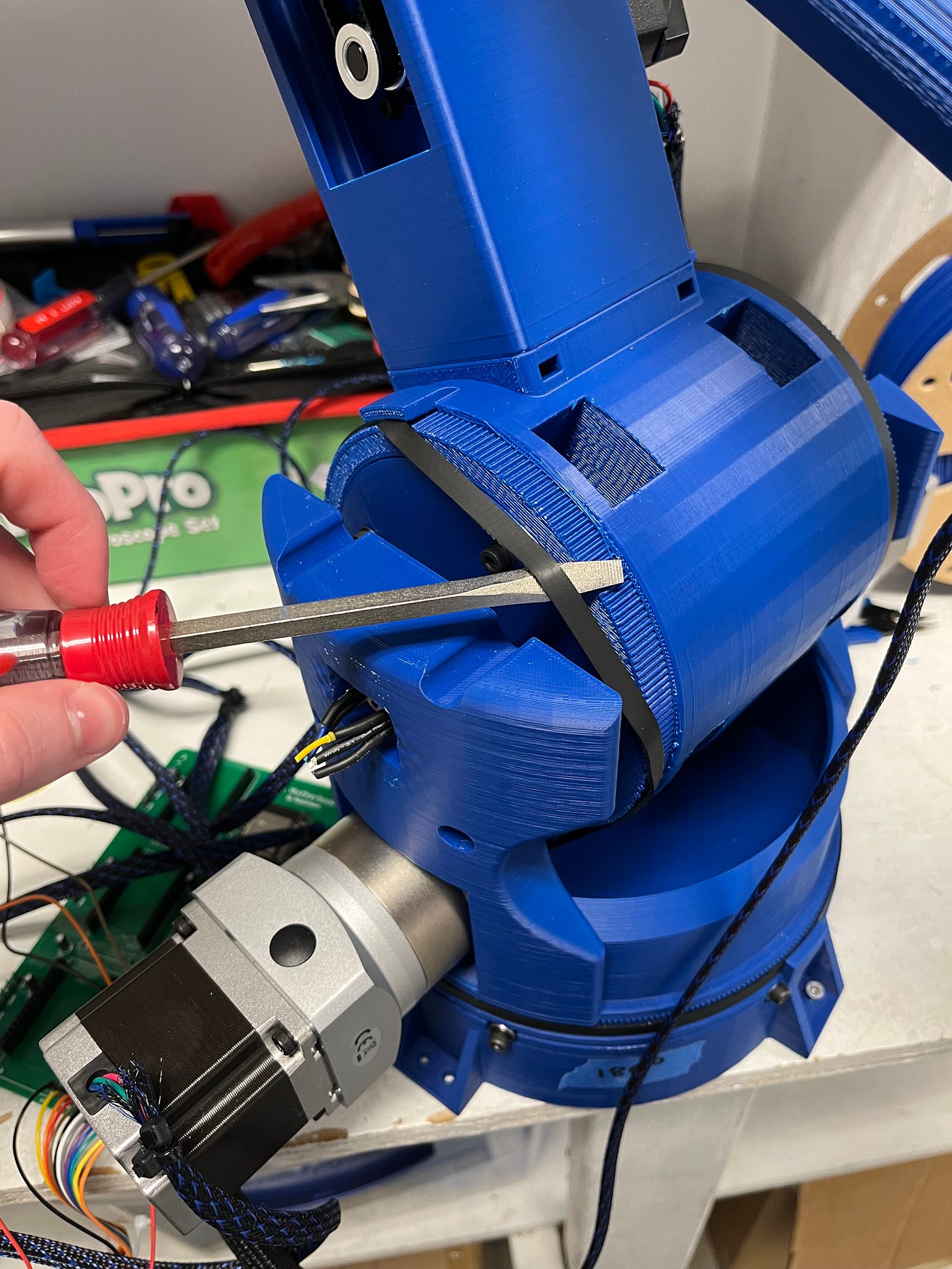
Now it’s time to move on to the first joint (J1 Base). We will want to start by attaching the custom pulley wheel I designed to the end of each NEMA-23 10:1 gearbox. This can be done by pressing the M5 nuts into the spaces for them on the inside of the pulley wheel, placing the pulley wheel over the respective place on the shaft so the holes line up with the end of each side of the keyway, then screwing a M5 bolt through each to keep it stable on the shaft.
After that, place each NEMA-23 through their assigned spaces and mount them using the same method.
With that done, we’re going to need to mount more bearings. Get two 20x47x14mm bearings and press them into their respective places on each side of the base component.
Next, insert each J1 Base mount attachment through the bearings.
Then, simply slide the J1 Base component over them and screw them in with some M4 nuts and bolts.
With that done you can add the next timing belts. There are only really two ways you can mount this because there are no tensors, and you still need it to be really tight.
The first method you can do is attach each end of the belt to the fitting at the top then try to brute force the belt over the end of the teeth to secure it. This step may take some trial and error because you want to make the belt as short as possible without making it so short that it becomes impossible to mount. I recommend starting long then slowly shortening it.
The other method, a bit easier, is force it as close as you can to the edge while each end is still fitted, then rotate the part downward while pressing inward to prevent slippage.
This method should be a bit easier. Just be sure that the belt length is as short as possible. It should be hard to do, but not impossible. If it feels like it is, you probably shortened it too much.
With that done you’ve successfully assembled the toughest joint! Nicely done.
This next part is easy. Just place the J1 component on top of J1 base and drop some bolts down. Insert the M3 nuts into their positions indented for them on the side of J1 Base, push them in with a screwdriver, and screw in the bolts you just dropped down the J1 component.
Next up, attach the 8mm bore pulley wheel to the NEMA-17 with the 5:1 gearbox, and screw it in place in its spot on the right of J1 which you just mounted. Use the same method with the M3 nuts and screws.
Then, time to mount more bearings. Grab two more 20x47x14mm bearings and fit them into their respective places on each end of J1.
Now grab both J2 mounts and insert them into their bearings.
Now you can slide J2 over them and screw them in place using some M4 nuts and bolts. There are places to fit the nuts on the inside as was done on the other joints.
Time for some more tensors to prepare for the next timing belt. Push some M4 nuts in the indention made for them at the top and thread in a M4 bolt with the 4x10x4mm bearing. Do this for both. This will keep the belt from slipping from low contact area.
Slide the next timing belt over everything using the same method as you did when mounting the timing belt for J1 Base. This may take some trial and error to get it fitted tight.
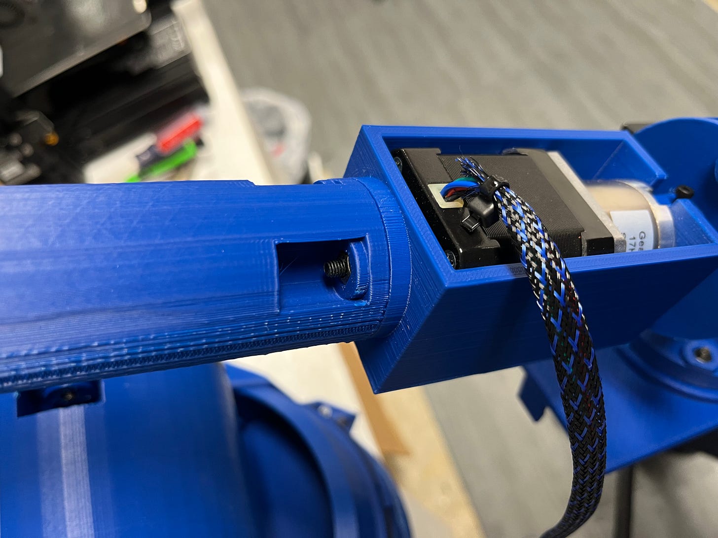
With that done, add the piece to house the NEMA-17 with the 27:1 gearbox to the end by securing it in place with some bolts and nuts. Be sure that the NEMA is secured as well, there are some holes in the end to ensure it won’t move.
You’re now on the last step, good work! :D
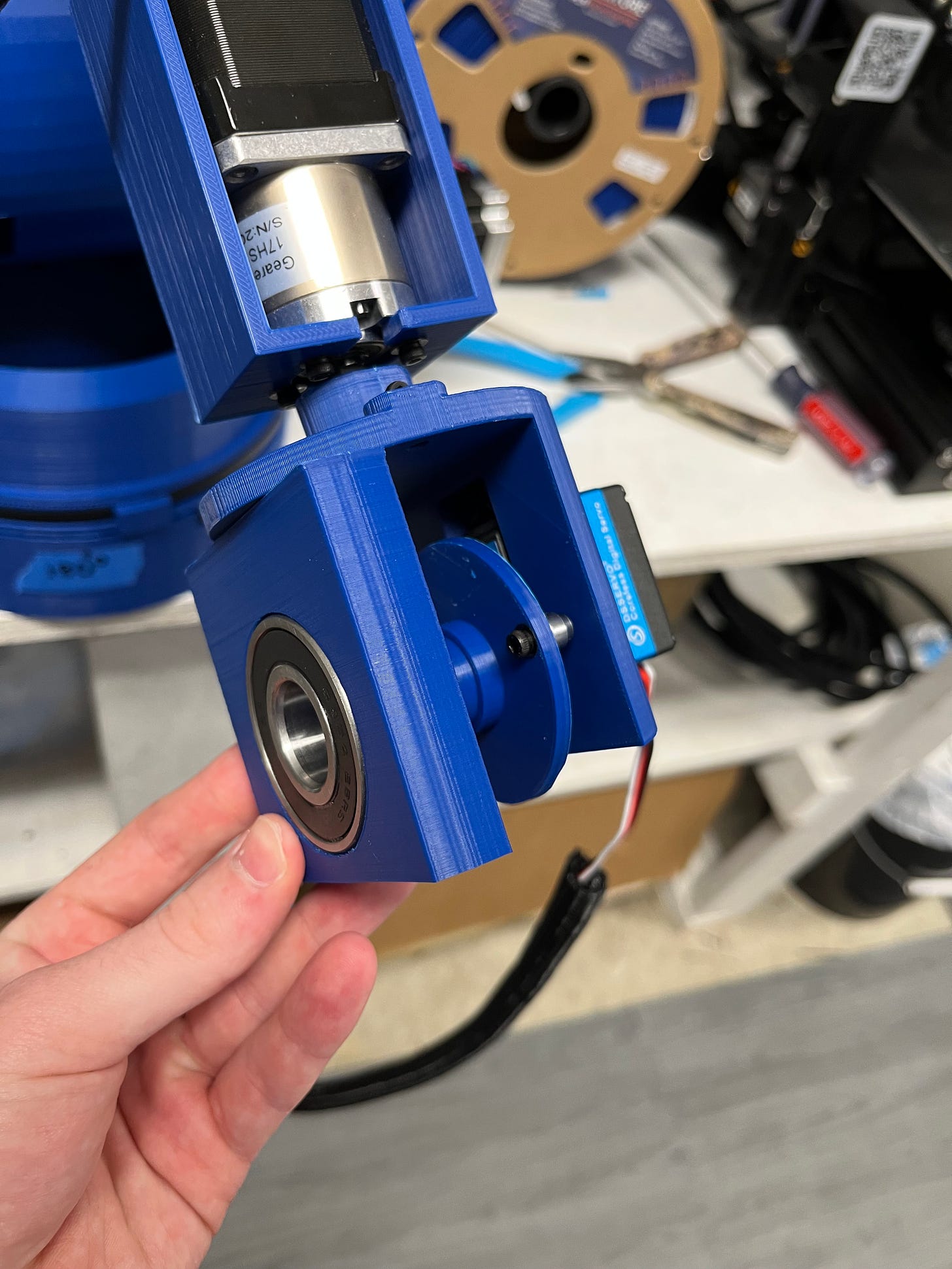
Grap the last piece and attach it to the shaft sticking out from the NEMA-17 with the 27:1 gearbox by inserting a nut and threading a M3 bolt through it so it’s stiff against the shaft. This will prevent it from sliding off and allow them to move together.
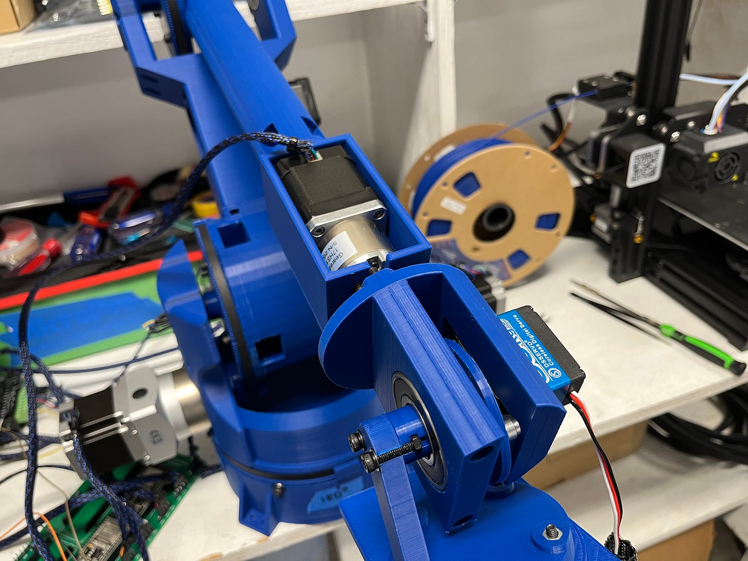
With that done, attach the 35kg.cm servo using some M3 bolts and nuts. You will then need to attach the servo horn to it, as well as the 3D-printed adapter that was made for it.
Now press fit a bearing to the servo mount component and push that through the adapter that was previously secured to the servo. Once that is done, screw it into the holes aligned for it at the bottom to prevent it from rolling/moving. This will help distribute gravitational weight off the servo so that it will be able to lift more.
With that done, push some nuts through each indenture at each end and attach the servo’s radial arm. There are some M4 nut indentations on the end of the servo arm so you can feel free to mount anything you’d like to it.
And just like that… CONGRATULATIONS! You’ve finished assembling ERA.
Thanks for sticking with me.
BOM
Bill of materials.
CAD files: Here (Thingiverse)
1 NEMA-17 Stepper Motor With 27:1 Gearbox (Feel free to get a smaller one)
2 NEMA-23 10:1 Planetary Gearboxes
Main expense of the project. If you’d like, your welcome to go deal hunting to try to find something cheaper. You just need to be very careful and make sure that the size of the outer/inner shafts are the same and that its total length and width are the same.
5 TB6600 Stepper Motor Drivers
Be careful buying ones other than what I linked! I previously bought one of these from a different brand and they have a knock off TB6600 IC. They still worked for the NEMA-17s but heated up super-fast and had issues.
The ones I linked are good for NEMA-17 & 23. Also feel free to get a different driver if you know your stuff. These are a little loud but work fine.
Arrangement of M3/M4 Nuts and Bolts.
I recommend just buying a kit if you don’t already have some.
It’s also important to note that you will need 4 M5x12 bolts and nuts for the custom pulley wheel. I just went to a hardware store since it was such a small amount.
2 Joysticks for the Controller (Any are fine, these were only sold in packs)
You will also need 2 switches, and 2 buttons.
A resistor, some capacitors and an LED would be nice to have but aren’t required.
24 AWG Wire to Power the TB6600s
You will also need some standard jumper wires if you don’t have any.
Disclosure: These are affiliate links. I get a portion of product sales at no extra cost to you.
Thanks so much for reading! I hope this was a helpful and informative article. If you decided to do the build, please feel free to leave any questions in the comments below. If not, I hope you were still able to enjoy reading and learn something new!
Have constructive criticism? I’m always looking to improve my work. Leave it in the comments! Until next time.
Instagram: RoboticWorx




















I love this, thanks for sharing your knowledge!